
L3 VPN Components
As was discussed in the Introduction section, it's often required to transport the traffic across the core for overlapping networks (a good example of this can be an ISP providing end to end connectivity for Customer A and Customer B).
In this case we will require some form of isolation and to better understand the concept, lets have a look at the following diagram
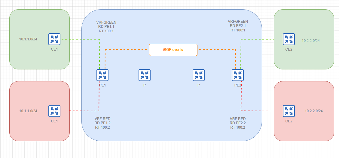
On this diagram we can see the following:
- MPLS Core represented by transit Provider routers (P) and Provider Edge routers (PE1 and PE2)
- Client A (Green) represented by Customer Edge routers (CE1 and CE2)
- Client B (Red) represented by Customer Edge routers (CE1 and CE2)
- Both clients require end to end transit and must be unaware of each other
Assuming that we already have a working MPLS core with all the required adjacencies built, lets think of how we can achieve this and the answer here is VRF
So what is VRF - simply enough a virtual RIB that allows to maintain isolated routing tables within the router and also exchange those routes over BGP extended communities.
First of all the IP VRF needs to be defined with a clear route distinguisher unique to each VRF. In our case we are going to create two - one for Client A (VRF GREEN RD RouterID:1) and for Client B (VRF RED RD RouterID:2). Here RouterID is unique to each PE and 1/2 are the VRF numbers.
Once the VRFs are defined on both PE1 and PE2, respective interfaces need to placed into those VRFs (in our case those are et1/et2). Those are going to be our peer links to clients and will result in the following directly attached VPN routes to appear in the BGP table of our PE routers
RouterID:1:PEERLINK |
RouterID:2:PEERLINK |
The next question is how do we exchange those routes between PE1 and PE2 and, most importantly, between the CE routers once we have peering built with the clients ? - Simple enough. We need to define what routes to export into what VRF and what to import from it. This is done under VRF definition on PE routers with route target attributes (think of those as of an additional "tag" added to BGP routes)
Summarizing our VRF definitions will look something like this
VRF GREEN | VRF RED |
RD RouterID:1 | RD RouterID:2 |
RT import 100:1 | RT import 100:2 |
RT export 100:1 | RT export 100:2 |
Once the above is done and our PE routers start exchanging route information for each of the VRFs it is time to bring up peering with clients (this can be done using pretty much any dynamic routing protocol with redistribution when needed)
After that our PE routers will make sure that routes learned from CE routers are isolated and carried across the transit network